 Русский
 English
The Rayevsky Hillfort
Ссылка на виртуальную реконструкцию.
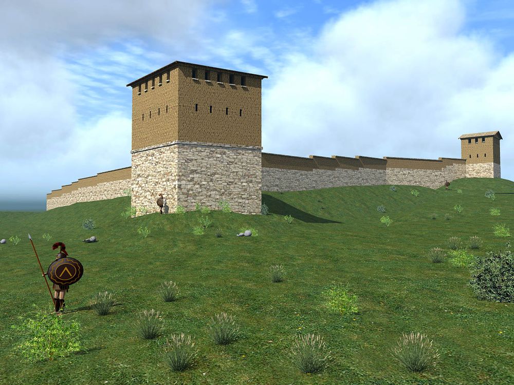
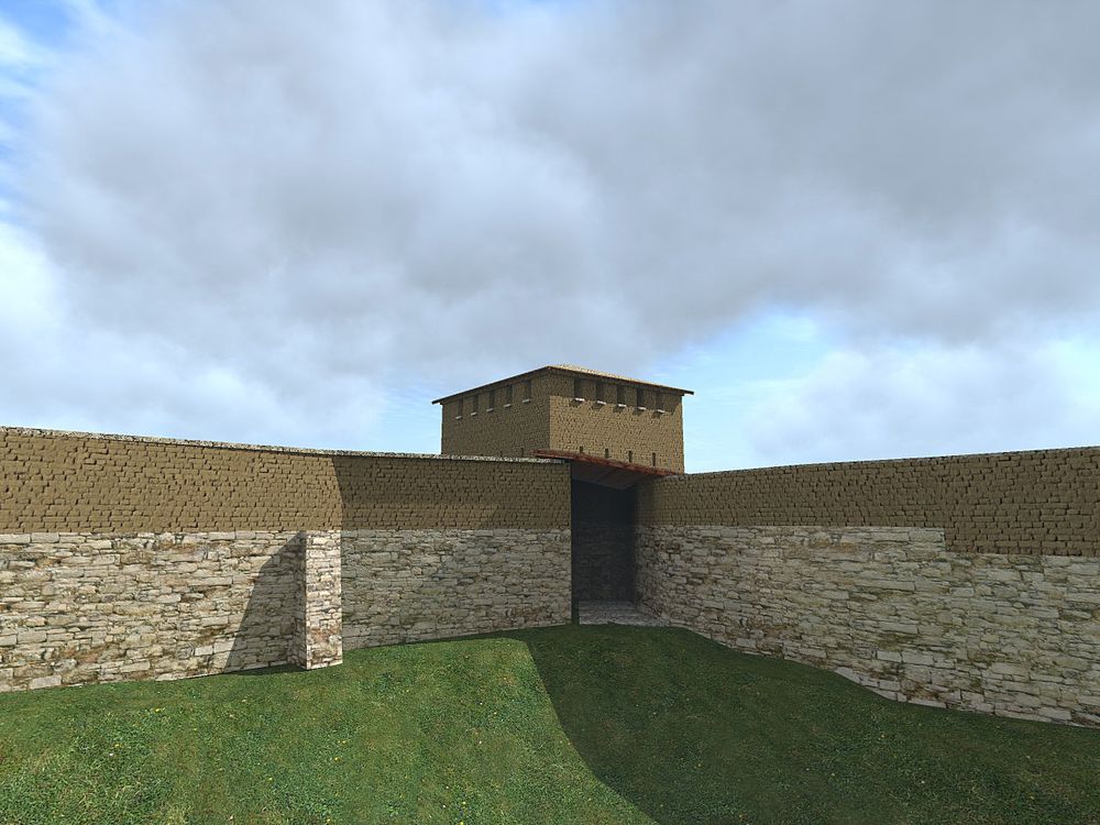
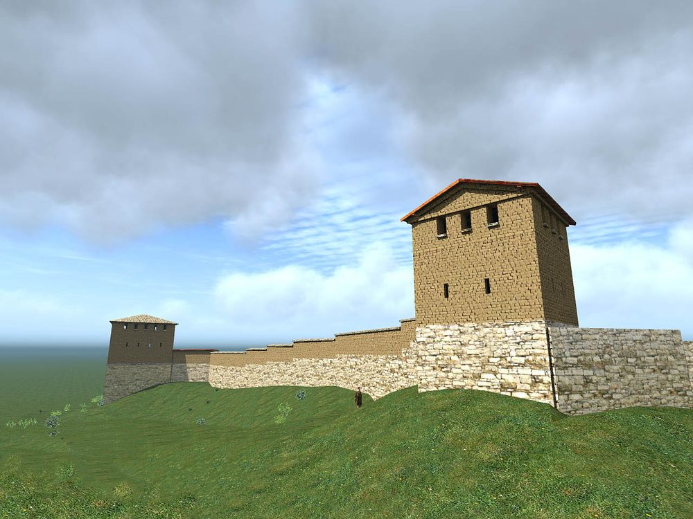
 Реконструкция Юго-восточной башни.
Сферическая панорама раскрытия восточной башни (август 2013).
 Фотограмметрическая модель раскрытия восточной башни (20 августа 2013). Если у вас Google Chrome нажмите правой “Сохранить ссылку как ” и просмотрите файл на своём компьютере.
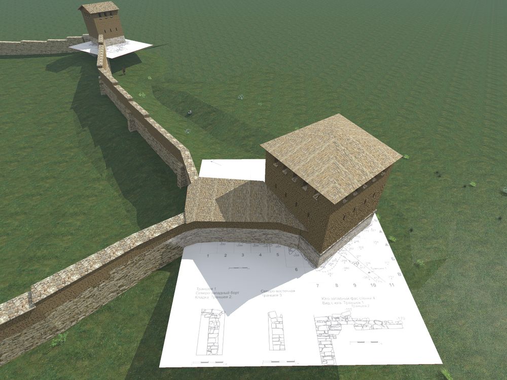
 Воссоздание конструкции башни на основании фотограмметрической модели (вид 1)
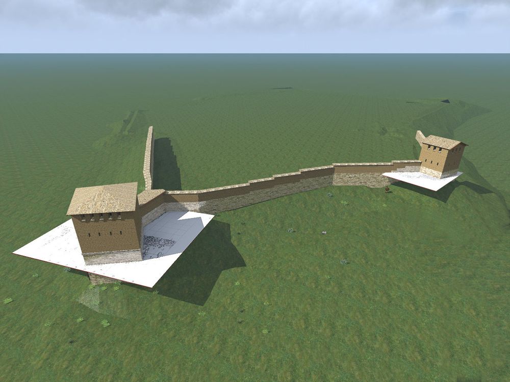
 Воссоздание конструкции башни на основании фотограмметрической модели (вид 2)
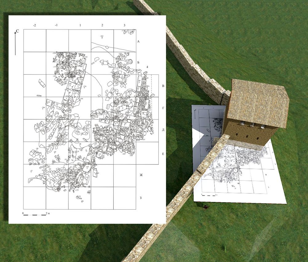
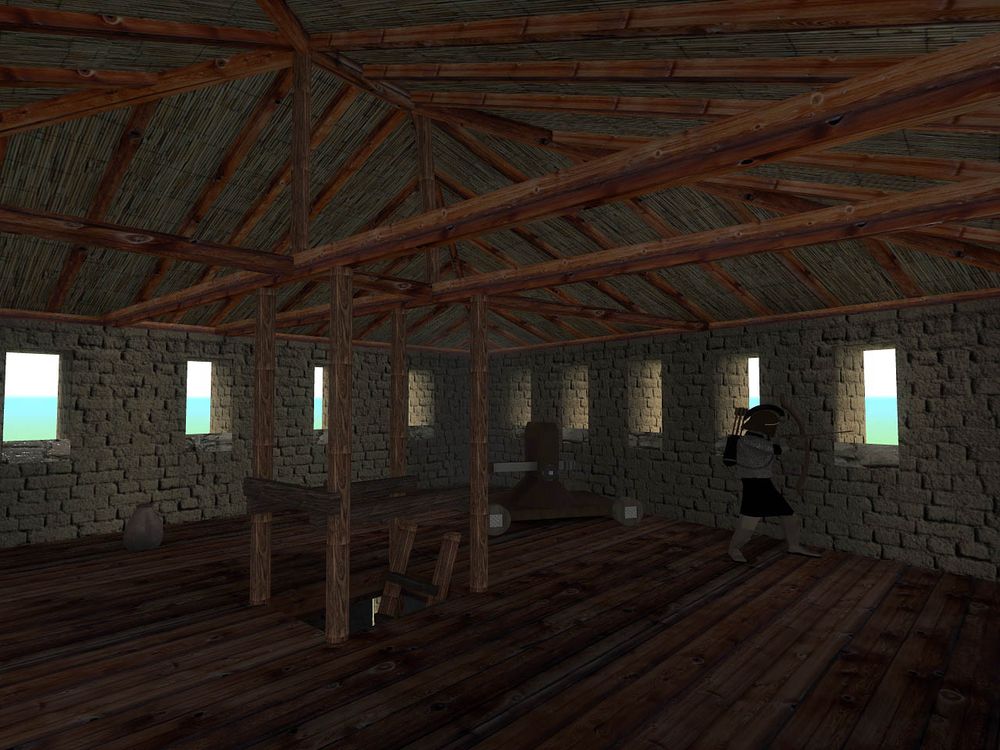
 Разрез восточной башни
One of the main objects of reconstruction is the history the Rayevski settlement, located in the vicinity of Novorossiysk. Its geographical location is identified here, structures and complexes indicate at its importance as an administrative center which the mainland peninsula had under its control.
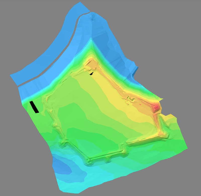
Рис.2. 3D модель современного ландшафта Раевского городища
(выполнена М.О. Жуковским)
The area of the settlement (within the mound) was 8.71 hectares. Along the perimeter it had been belted by defensive walls, which included nine towers. The towers are spread unevenly along the walls, concentrating mainly along the south wall of the settlement and along south stretches of the west and east walls ‒ in the areas of the most vulnerable terrain. At least three towers (East, Southeast, Southwest) had a rectangular stone plinths.
The north part about 185 m about 35 m long steep , about 35º slope, to the river Maskaga, 32-35 m high. On this slope, near the capes crest is now found the unused ascent to the fort, about 2-3 m, thick and the ending at entrance. The upper part of the entrance fortress gets to the foundation wall and follows along its foot to the east-west about 40 meters.
On the citadel located in the northeast corner of the fort was found the foundation of two defensive walls, about 1.8 m thick, forming a right angle. It allowed to determine its size and imagine what was situated on the protected territory: a building with the size of 12 × 22 m (area – 252 m2), and a small yard to the south. The total area of the Citadel is 650 m2. The location of the entrance into the citadel had not been found. A gate was found on the eastern side. Judging by the level of the stone dam on the outside wall the surface was cut in antiquity (scarped).
In Novorossiysk an expedition of the Institute of Archaeology of RAS in 2013 along with traditional instruments fixing the excavations a team of authors has tested one of the most promising technologies to record information – the so-called photogrammetry techniques, the results of which were the basis for the construction of three-dimension models for the virtual reconstruction. This method is based on algorithms for the automated construction of three-dimension models on the basis of photographs, filmed along the perimeter of the object. The first stage of work was a detailed survey by the Canon 60D camera with lenses of 10 mm and 22 mm of the Rayevsky separate towers on the perimeter of the settlement at certain time period at the time of uniform illumination (before the sunrise). Then in the program Agisoft Photoskan Pro the photo processing was conducted in the following steps:
a) Snap photos to each other. The photographs marker shows the contours and angles of individual items that the program on the following photos should automatically recognize;
b) Creation of a cloud of points. After snapping photos the program created a cloud of point with the geometry of the construction;
c) Creation of the geometry of the construction. A similar cloud of points was obtained during laser scanning;
d) Creation of the texture on the basis of photographs.
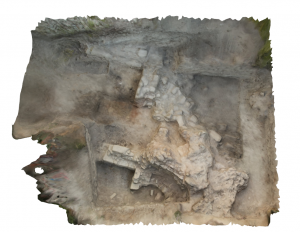
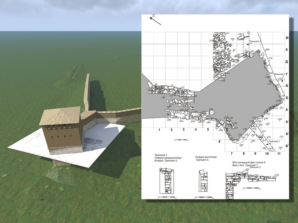
Рис. 3. Пример башни Раевского городища, созданной с помощью технологии фотограмметрии. Вид сверху в программе Adobe Reader. Нажмите для просмотра. В google chrome нажмите правой клавишей мыши и нажмите “Сохранить ссылку как” и просмотрите файл на своем компьютере.
The process of building high poly model based on the tower photogrammetry technology took from 4 to 6 hours on the laptop and it was performed by the expedition scientists on the site.
Created by the photogrammetry technology three-dimension model will serve to two tasks, one of which is the basis to build a three-dimension model, the second ‒ a source attached to the documentation for further analysis and work with it. Photogrammetric models allow the most accurate way to transfer geometry models. Their a distinctive feature is an ability to pass complex geometric shape of the object, which is problematic to draw by hand, in the programs of computer-aided design CAD (computer-aided design).
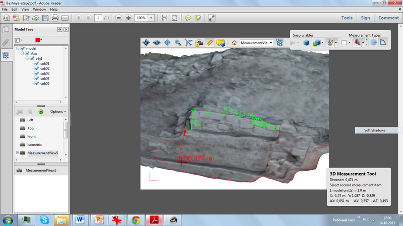
Рис.4. Пример разреза башни Раевского городища с замером отдельных элементов в программе Adobe Reader. Разрез выполнен с помощью инструментов Adobe Reader.
Let’s start with the second task. Construction of three-dimension model using hotogrammetric techniques cannot be, in our view, an end in itself of the study because In this case, the model can be replaced by a good photograph. The immediate task at this stage of work we see the construction of the working tools with the model for this purpose. For this purpose the created 3D model has been exported from the program Agisoft Photoskan Pro format.U3D, after that the model was imported into the program Adobe Acrobat X settings view from 3 sides + view ISO. In some cases, in order to finalize the detailed model, and correct the texture directly on 3D models, the program Meshlab was used. To do it the export of the program Agisoft Photoskan Pro was made in the format .obj, opened in Meshlab and then exported into U3D in and imported into Adobe Acrobat X.
The created 3D model in .pdf format can be viewed in the program Adobe Reader. Starting with version 9.0., a tool to analyse size and to construct the model cut is integrated into the program. Each element of the model in addition to the size of the signature may contain a text description. If necessary, the program allows us to change the lighting, turn the model in a black and white drawing, etc. In our case, for the correct lighting of the model we used lighting setup Cube Light. The Adobe Acrobat X program has various possibilities of representation model and its analysis, we will not dwell on their description in details. After the required markings in the Adobe Acrobat X program the model is stored in .pdf and attached to the archaeological documentation with already integrated analysis tools.
Let us turn to the description of the first task – the construction of a three-dimension model based on photogrammetric model. To solve this problem the authors of the program Adobe Photoshop merged «metrovkas» (the metric system of counting) and plans of the excavation. As a result the received plan was kept in the .jpg format and imported into 3D program of the ArhiCAD program.
Then the photogrammetric models were imported in to ArhiCAD, drawings and sections of the excavation were. In some cases, when comparing several drawings digs and three-dimensional photogrammetric model reveals a number of inconsistencies were found. Further, based on the drawings contours, models and photogrammetric data of the photo of the settlement its walls were erected.
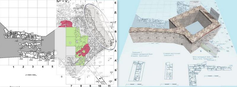
Рис. 5. Слева. Результат наложения метровок на план раскопа в программе Adobe Photoshop CS3. Синим цветом выделен фрагмент разницы между двумя планами раскопа. Справа. Результат созданного фундамента на базе чертежей раскопа и фотограмметрии.